Search
Introduction:
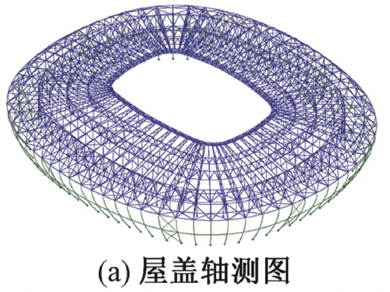
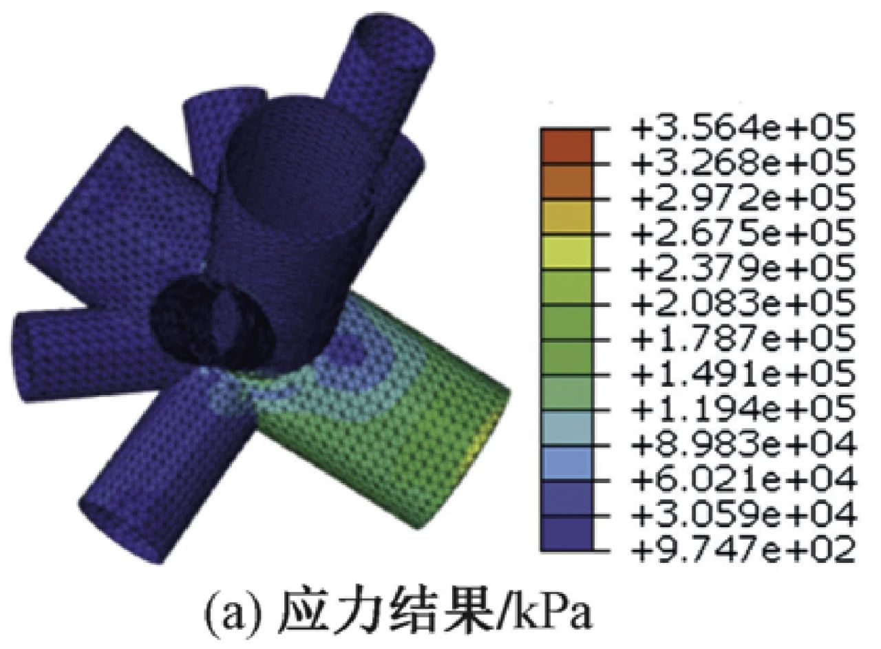
The main structure of Chongqing Longxing Football Stadium adopts the frame structure with a small amount of shear walls, and the steel structure of the roof adopts the suspended plane truss + the stable support of the upper and lower strings + the single-layer grid structure of the facade. In order to study the difficulty of structural design, SPASCAD-PMSAP, MIDAS Gen (Ver.2019) and SAP2000 design software were used to analyze the seismic performance of the structure under multiple earthquakes. SAUSAGE and SAP2000 software were used to analyze the seismic performance of the structure under fortification and rare earthquakes. ANSYS software is used to analyze the overall stability of the steel roof, and ABAQUS software is used to analyze the mechanical performance of the joint. The results show that the structure has good anti-seismic ability and anti-continuous collapse ability, and the structure design is safe, reasonable and economical.
Chongqing temperament of the football palace - Longxing football Stadium unlimited structure design
By LI Jinzhe, Feng Yuan, SHI Weinan, GUO Chi, et al
01 Project Overview
Chongqing Longxing Football Stadium is located in Longsheng District in the east of Chongqing city and north of the Yangtze River. It is the venue for the 2023 Asian Cup. Based on the design concept of "the football palace of Chongqing temperament", the planning, landscape and architectural design include elements such as converging, rotating and rising smooth curves. The architectural rendering of the football stadium is shown in Figure 1. The total construction area of the football field is about 160,000 m2, with 4 floors on the ground and 1 basement floor in some areas. Four anti-seismic cracks are set to separate the main body of the football field from the outdoor stairs. The installation of anti-seismic cracks is shown in Figure 2. The main body of the football field is a concrete frame structure with a small amount of shear walls [1]. The plane layout of the first-floor structure is shown in Figure 2 and the section diagram is shown in Figure 3. The plane of the football field is elliptical, the plane size of the first floor platform is 267m×235m, and the plane size of the first floor is 235m×203m. The total height of the concrete main structure (from the top of the foundation to the top of the concrete stand) is 42.365m (taking the highest point of the top of the concrete stand). In order to ensure beauty and function, the entire concrete main structure is a structural unit without expansion joint [2], but design and construction measures must be taken to prevent cracking of the ultra-long structure caused by temperature stress. The steel roof of the football stadium is oval, and the structure is suspended plane truss + stable support of upper and lower strings + single-layer grid structure of the facade [3], a total of 68 plane trusses, the cantilever length of the trusses is about 54 ~ 58m (including 54m above the center point of the north and south stands, 58m above the center point of the east and west stands), and the length of the steel roof unit is about 283m. The width is 252m. The steel roof is supported on the lower concrete main structure by finished cast steel supports [4].
02 Roof steel structure
The height of the steel roof of the football field is about 59.05m (take the average height of the top of the truss), and the composition of the steel roof is shown in Figure 4. The overhanging plane truss [5] structure is adopted for the awning of the football field, which is simple and regular, and is suitable for the special effect of the infield of the building. The canopy truss structure consists of 68 trusses. 68 pillar support trusses are installed on the concrete structure at the end of the stand. In order to satisfy the simple and transparent effect of the building, 68 rectangular curved rods and 1 horizontal tie rod are adopted to form a single-layer grid structure of the facade, which provides multi-point support for the outer ring of the roof. The rectangular curved rods also serve as the support of the curtain wall structure. The radial trusses in the awning area are arranged as follows: the height of the inner cornice truss is 2.0m, and the height of the support truss is 11-13m; The radial cantilever members of the roof are divided into 9 intersections, and the balance transition members are divided into 3 intersections.
Five ring trusses are set up in the awning to provide the ring stiffness of the roof, namely one inner ring three-dimensional truss, one axis truss, one balance section tail truss and two overhang section plane trusses. The inner ring three-dimensional truss can effectively improve the overall stiffness of the inner ring of the roof. The cantilever span of the roof is large, and setting two plane trusses in the middle of the cantilever section can not only further reduce the out-of-plane calculation length of the chords under pressure, improve the economy, but also provide lateral constraints for the plane trusses, and minimize the influence on the building effect. The axial truss and the balance section tail truss can effectively improve the torsional stiffness and bearing capacity of the whole canopy structure. In order to improve the overall stiffness in the roof plane of the awning area, 8 sets of horizontal roof struts are set symmetrically, and the struts are also added in the corresponding area of the balance transition section. The rectangular curved bar in the facade of the structure provides the vertical support of the roof, and the horizontal tie bar and diagonal brace bar in the facade can greatly improve the torsional rigidity of the structure.
When designing the structure, the calculated length coefficient μ is calculated according to section 5.3 of the Design Standard for Steel Structure (GB 50017-2017) [6] and section 5.1 of the Technical Specification for Space Grid Structure (JGJ 7-2010) [3]. According to the existing eigenvalue buckling analysis results, the Euler critical force Pcr=π2EI/(μL) 2 (E is the elastic modulus, I is the cross section moment of inertia, L is the length of the member) of the compression bar is obtained, and the length coefficient of the member is deduced by Euler formula.
03 Major load and seismic parameters
The seismic fortification intensity of this project is 6 degrees, the design basic seismic acceleration is 0.05g, the design earthquake group is the first group, the site category is class II, and the site characteristic period is 0.35s. According to the Classification Standard for Seismic Fortification of Building Engineering (GB 50223-2008) [7], this project belongs to a super large stadium, the main structure belongs to the key fortification category, and the seismic measures are adopted according to 7 degrees.
The values of floor and roof loads shall be determined according to the Load Code for Building Structures (GB 50009-2012) [8]. Stadium canopy [9] suspension truss upper string (sunshine panel) additional constant load 0.9kN/m2, roof balance section truss upper string (metal roof + decorative grille) additional constant load 1.3kN/m2, roof balance section ceiling additional constant load 0.8kN/m2, canopy suspension truss lower chord film and connector vertical force 0.7kN/m, The horizontal tensile force of the lower chord film of the overhanging truss of the awning is 1.0kN/m, the dead load of the facade curtain wall system and the connecting parts is 1.0kN/m2, and the dead load of the bridleway and lamp bridge is 3.0kN/m. The live load of steel roof is 0.5kN/m2, the live load of gutter is 3.2kN/m, and the live load of bridleway is 3.5kN/m. Performing load (as a separate working condition check) : the vertical force of Wiya hanging point is 15kN, the horizontal force is 70kN, and a lifting point is set at a distance.
The basic wind pressure is taken as W0 = 0.45kN/m2 according to the recurrence period of 100 years, the ground roughness category is Class B, and the shape coefficient of wind load and wind vibration coefficient are taken as values according to the wind tunnel test. The wind tunnel test model [10] is shown in Figure 5. The maximum wind suction equivalent static wind load of the inner roof is 1.32kPa and the corresponding wind direction Angle is 80°. The maximum wind pressure equivalent static wind load of the outer roof is 1.97kPa and corresponding wind direction Angle is 280°; the maximum wind suction equivalent static wind load is 3.36kPa and corresponding wind direction Angle is 210°. The maximum wind pressure equivalent static wind load on the facade is 2.06kPa, corresponding to 190° wind direction, and the maximum wind suction equivalent static wind load is 1.82kPa, corresponding to 320° wind direction.
According to Appendix E.5 of Code for Load on Building Structures (GB 50009-2012) [8], the basic temperature in Chongqing is 1~37℃, and the extreme temperature is -1.8~43.0℃. The surface of the steel structure of this project chooses a light-colored finish, which has a strong reflection ability of solar radiation, so the temperature rise value caused by solar radiation is 10℃. Considering the difference between indoor and outdoor temperatures, the climate temperature that concrete structure and steel structure may encounter is determined: concrete structure indoor 10~30℃, outdoor 0~38℃, steel structure 1.8 ~ 43℃. Structure design closing temperature range: concrete structure 5~20℃, steel structure 18~25℃. The indoor temperature rise of concrete structure is 25℃ and the temperature drop is -10℃, and the outdoor temperature rise of concrete structure is 33℃ and the temperature drop is -20℃. The extreme temperature of the steel structure outdoor canopy: temperature rise 25℃, temperature drop -26.8℃ (take -27℃), considering the solar radiation temperature rise to get a comprehensive temperature rise of 35℃.
04 Basic Design
The design grade of the football field foundation is Class A [11], and the top elevation of the foundation is about -6.000m. From the level of the site to the elevation of the building floor, the rock in the excavated area is exposed, and the independent foundation under the column is adopted, and the medium-weathered rock is used as the foundation bearing layer. The north side of the site is a filling area with a maximum filling depth of about 12m. According to the suggestion of the geological survey report, the foundation of cast-in-place pile with rotary excavation holes is adopted, and the medium-weathered rock is taken as the bearing layer, and the negative friction resistance is considered in the design. The standard value of natural compressive strength of medium-blown sandy mudstone is 9.78MPa, and the characteristic value of foundation bearing capacity is 3550kPa. The standard value of saturated compressive strength of medium weathered sandstone is 25.88MPa, and the characteristic value of foundation bearing capacity is 9394kPa.
The independent foundation [12] and strip foundation are all embedded in the rock layer, and the foundation is cast in the original trough. In the north pile foundation area, a structural bottom plate is set between piles to enhance the integrity of the structure. As shown in Figure 6, the filled area is mainly independent foundation, and other areas are mainly pile foundation. The overlying soil layer on the site is mainly plain filled soil and silty clay, and the groundwater on the site mainly belongs to bedrock fissure water and upper stagnant water, and there is no uniform free water level. The plain filled soil has permeable property and the drainage condition of the site is good. During the construction, attention should be paid to the surrounding drainage and the backfilling process of the foundation pit (fertilizer tank). 3:7 lime soil backfill is adopted, and the quality of backfill is controlled strictly according to the Code for Design of Building Foundation (GB 50007-2011). The compaction coefficient of backfill is 0.94; Prevent the upper layer stagnant water, surface water seepage through the fertilizer tank to the base, and make the surface closure measures, without considering the foundation anti-floating.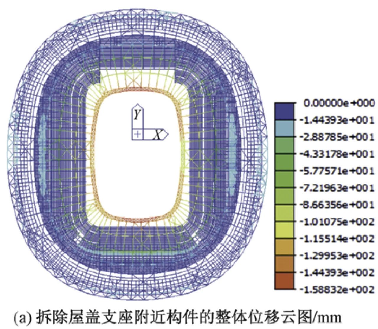
05 Calculation and Analysis
5.1 Structural seismic performance analysis
The design and analysis of structural elastic stage (frequent earthquake) were calculated by the software SPASCAD-PMSAP (V5.1 version), MIDAS Gen (Ver.2019) and SAP2000, respectively. The analysis of elastoplastic stage (fortification, rare earthquake) is calculated by SAUSAGE and SAP2000 software. The overall stability of steel roof was analyzed by ANSYS finite element software. The shear wall at the bottom of the football field bears the overturning moment of 58.7% (X direction) and 68.0% (Y direction), but the shear wall does not meet the spacing requirements stipulated in the Technical Regulations for Concrete Structures of Tall Buildings (JGJ 3-2010), so the envelope design is carried out according to the frame structure and the frame structure with a small amount of shear walls.
Under frequent earthquakes, the shear weight ratio of the structure is 3.26% (X direction), 4.28% (Y direction), the maximum interstory displacement Angle is 1/2636 (X direction), 1/2253 (Y direction), the maximum interstory displacement ratio is 1.34 (X direction), 1.33 (Y direction), the maximum axial compression ratio of the column is 0.73, and the maximum axial compression ratio of the shear wall is 0.12. Other overall indexes such as cycle ratio, lateral stiffness ratio and floor shear bearing capacity ratio meet the requirements of "Technical Regulations for Concrete Structures in Tall Buildings" (JGJ 3-2010). Under rare earthquakes, the ratio of the peak value of the base shear obtained from the elastic-plastic analysis to the peak value of the base shear obtained from the elastic analysis is 0.83 in the x-direction and 0.84 in the Y-direction, which indicates that some members of the structure enter the plasticity and dissipate part of the seismic energy under the action of rare earthquakes. At the same time, the stiffness of the structure decreases and the seismic action decreases, but the overall plasticity of the structure is light from the ratio.
5.2 Supplementary analysis of key components
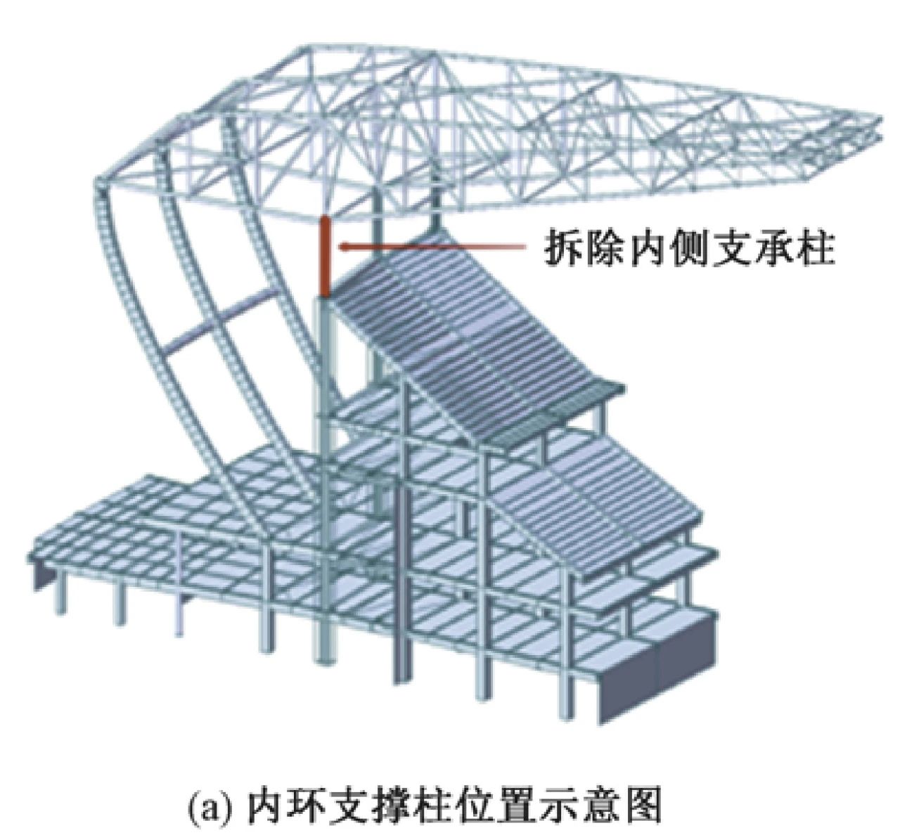
The supporting column of 1-G axis of the steel roof is the key component, and the length of the supporting column is about 4.7~13.4m because of the different connection position with the lower concrete structure. Considering the uniformity of the stiffness of the support column, the larger steel column [13] has a cross-section of 1400 (cylinder) and an internal cross-section of 1000×300×38×38 (cross section). The shorter column has a cross-section of 1000 ϕ (cylinder) and an internal cross-section of 600 x 200 x 38 x 38 (cross section).
Using MIDAS Gen software, the buckling analysis of cross-layer columns was performed. The buckling mode of the 1-G axis support column is shown in Figure 7. Taking the unfavorable axial force of ϕ1000 in short steel column and ϕ1400 in long steel column under D+L (dead + live load) load combination, calculate the length of each component of 1-g axis support column and calculate the length coefficient according to Euler's critical force formula. The results are shown in Table 1. In the design, the constraint effect of the upper steel structure on the 1-G axis support column is not considered, and the calculation of the length coefficient is calculated according to the calculation result of buckling analysis and the envelope value of 2.0.
The expected performance of the frame column supporting the roof is medium shock elasticity in normal section and non-yielding in large earthquakes. CisDesigner software was used to check the components, and the internal forces were taken from the unfavorable internal forces in PMSAP and SAUSAGE software. Based on the additional initial eccentricity caused by the eccentricity of the member itself, the installation error of the upper finished cast steel support of 100mm is considered. The yield surface of steel column can be obtained by considering the second-order effect and the actual reinforcement of steel column. Figure 8 and 9 show the P-M-M sphere envelope results with ϕ1000 column and ϕ1400 column, respectively. It can be seen from the figure that all internal force points in the figure are far from the sphere limit line, and the stresses in ϕ1000 column and ϕ1400 column are relatively small, meeting the performance target requirements.
Table 1 The calculated length of each member of the 1-G axis support column and the calculated length coefficient
5.3 Multi-point and multi-dimensional seismic response analysis
Due to the length of the main concrete structure, the multi-point and multi-dimensional seismic response analysis considering the travelling wave effect and multi-dimensional ground motion is carried out. The frequency diagram (X direction) of descending wave effect coefficient of steel truss under artificial wave (RH2TG035) is shown in Figure 10. As can be seen from the figure, the traveling wave effect coefficients of the components are mostly distributed between 0.5 and 0.8, with a small part greater than 1 and the maximum not exceeding 1.4. Since the seismic action does not control the effect, the seismic action is properly amplified and reviewed during the design.
The frequency diagram of downgoing wave effect coefficient (X direction) of frame column under artificial wave (RH2TG035) is shown in Figure 11. As can be seen from the figure, for the bottom frame column, the traveling wave effect coefficient of its components is about 0.3 ~ 0.6, and a small part is 0.9 ~ 1.1. Since the seismic action does not control the effect, the seismic action is properly amplified and reviewed during the design.
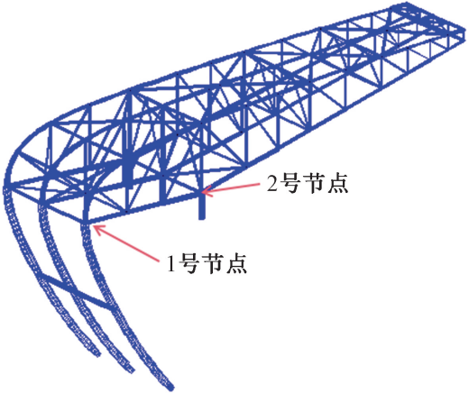
5.4 Calculation and analysis of roof steel structure
5.4.1 Static analysis results
According to the importance of the building and the layout of the structural scheme, the importance levels and performance objectives of the components are determined. The roof structure is divided into key components, important components and general components according to Table 2. According to the different importance of the component, different stress ratio control indexes are set. The control stress ratio of the key component is 0.75, the control stress ratio of the important component is 0.85, and the control stress ratio of the general component is 0.9.
Table 2 Definition of importance of steel structure members
The vertical displacement of steel roof under typical working conditions is shown in Table 3. As can be seen from the table, under the combined conditions of 1.0 constant +1.0 live load, the torsion span ratio of the steel roof is 1/299, which meets the requirements of structural stiffness. The main sections of the structure are as follows: ϕ273×14, ϕ299×18, ϕ325×16, ϕ450×20, ϕ450×22 of the suspension truss chord section; Suspension truss belly bar section ϕ133×8, ϕ203×12, ϕ325×18; Balance section truss chord section ϕ560×25, ϕ600×30; The balance section truss belly bar section ϕ377×11, ϕ402×18; Rectangular curved rod section 1200×600×38×38; Horizontal tie bar area ϕ700×35.
Copyright © Zhejiang Wanhao Group Co., Ltd. All Rights Reserved.
Sitemap | Technical Support 