Search
Project Name: Membrane Structure of "Storm and Storm" in Dream Valley of Hengdian Film and Television City
Construction site: Jinhua City, Zhejiang Province
Completion time: August 2012
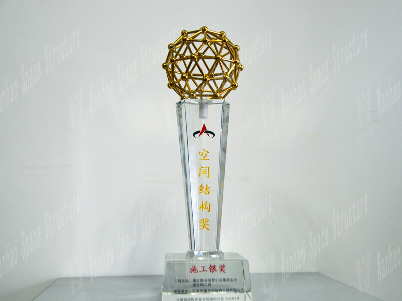
Award grade: Construction Silver Award
Winner: Ningbo Wanhao Space Structure Engineering Co., Ltd.
I. Project Overview
The membrane structure project of the "Rainstorm" in Dream Valley is located in Hengdian Town, Dongyang. The building area is about 6,600 square meters, which is a relatively large color film structure project in China. The geometrical shape of the steel structure roof of the stand is fan-shaped, with the structural columns horizontally as the dividing line, which is divided into two major parts: the first half is a cantilever structure part, and the second half is a "V" bracket structure part. The main beam of the front cantilever structure is in the form of a truss, and is connected by an arc tube in the lateral direction. The maximum cantilever length of the main beam is 32 meters. The second half of the secondary beam uses the front half of the truss to extend longitudinally and is fixed in the form of a "V" bracket on the bull's leg embedded in the stands.
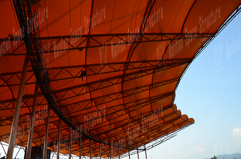
Membrane Structure of "Rainstorm" in Dream Valley
The project was designed, manufactured and installed by Ningbo Marriott Space Structure Engineering Co., Ltd. The project was completed in August 2012.
Structural system
The "Rainstorm" stands in Dream Valley is a skeleton-supported membrane structure. The skeleton steel structure consists of a 15 榀 main truss and 154 arc tubes, and is made of round steel pipes.
The total length of the main truss is 62.5 meters, and the cantilever is 32.7 meters. It mainly bears axial forces. The truss is connected to the column by a round pipe as a tie rod, which reduces the beam end displacement and enables the truss to perform better. It's functional. The main truss supports most of the weight of the whole structure, and also serves as the fixed edge of the membrane material, so that the membrane and steel can be tightly connected together.
The main trusses are connected by an arc tube. The arc tube adjusts the internal force distribution between the main trusses and acts as a lateral support for the main trusses, transmitting lateral horizontal loads and improving the stability of the overall structure. The arc tube has an arch shape with a sagittal height of 1m to 1.5m, which can better support the membrane surface and make it more capable of self-draining rain and snow.
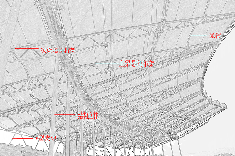
Steel structure skeleton
The membrane structure part consists of a total of 28 membrane materials. Each membrane material is fixed to the main truss with M10 stainless steel high-strength bolts. The junction between the membrane and the membrane is sealed with a 25cm wide waterproof membrane to connect the entire roof system. As a whole, it meets practical, stable and beautiful design requirements.
3.1 Structural design
Calculation diagram
The engineering membrane structure and the corresponding supporting structure all take the internal main structure as a carrier and are supported by the membrane body and related structures. The 3S3D11.0 design software is used for analysis. The calculation diagram is shown in Figure II-19-8. Consider a constant load of 0.01KN / m2, a wind load of 0.55KN / m2, a snow load of 0.35KN / m2, and a live load of 0.3KN / m2.
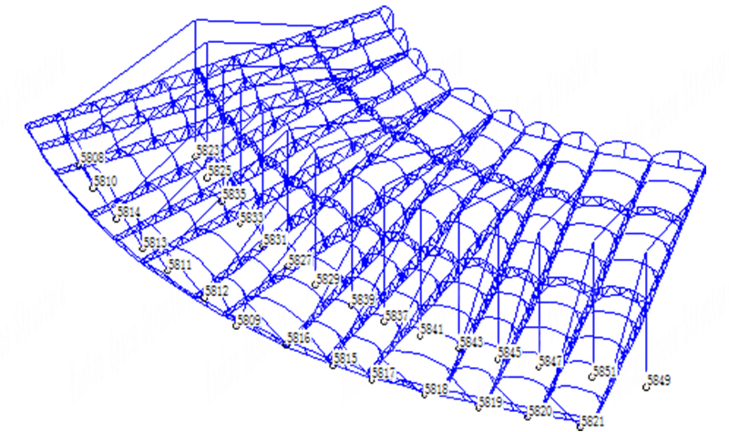
Computational diagram (circle indicates support, number is node number)
2. Membrane stress and calculation results
The design value of the strength of the membrane is 20.0 MPa according to the first type of load effect combination, and 40.0 MPa is calculated according to the second type of load effect combination.
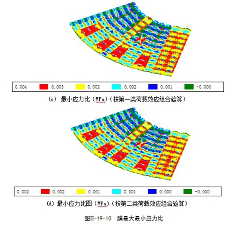
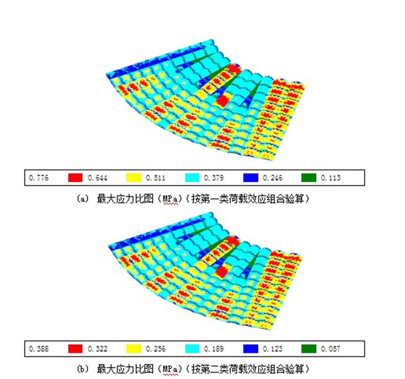
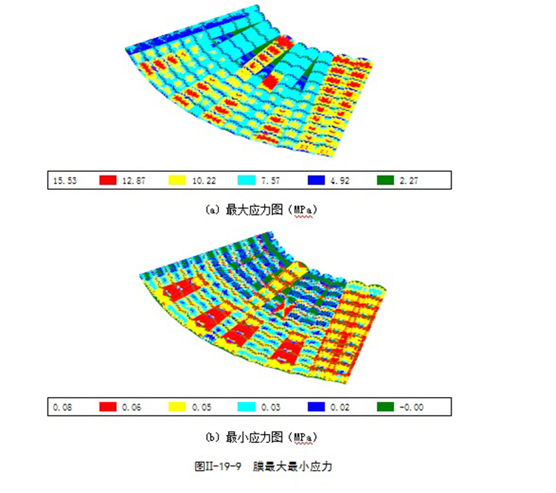
3.2 Technical measures for steel structures
1. Engineering Features
⑴ The roof structure of the grandstand is a large-scale color film structure project in China, the steel structure is a special-shaped space structure, and the steel columns are fan-shaped. The accuracy of the measurement is very high, which greatly increases the difficulty of lifting. The membrane structure is very sensitive to the error range of the steel structure hoisting. The error is too large, which may cause the discrepancy between the steel and the membrane.
The maximum height difference between the steel structure and the ground is 35m. At the same time, due to the site conditions, the scaffolding can not be set up, which also greatly increases the construction difficulty of the membrane structure.
2. General construction flow and overall deployment
The main steel structure of Hengdian Film and Television City Dream Valley Rainstorm Torrent Stand Membrane Structure Project is divided into 15 架 main truss, fan-shaped arrangement, the roof is saddle-shaped undulations, the main truss cornice is the highest (+ 35m), comprehensive factors such as component weight, installation Radius, structural stability and wind resistance during installation, etc. The main structure is divided into vertical members (embedded parts, main structural columns, "V" brackets), radial members (cantilever truss, arc tube) . Except that the embedded parts are installed separately, the other parts are hoisted on the ground as a unit. In order to ensure the stability and safety of the structure during the construction phase, it was determined that after the installation of the embedded parts, the main structural column and the "V" bracket were hoisted in advance, and the secondary beam extended the truss and the main beam. The overall construction process of cantilever truss integrated hoisting by unit.
According to the actual situation of the project, the overall plan layout was researched, that is, the "V" brackets and secondary beam extension trusses were concentrated on the outside of the stands, and the main beam cantilever trusses and horse tracks were made on the inside of the stands. This can speed up the production of primary and secondary beam trusses and facilitate assembly.
3. Node installation form
Designing a reasonable node installation form is not only the key to ensuring the quality of the project, but also the key to improving the efficiency and shortening the construction period. In view of the large number of pipe-to-pipe intersecting nodes and tube-ball nodes in this project, which have various forms and high welding requirements, the functions of the installation nodes are analyzed as follows: that is to meet the mechanical requirements of the construction and permanent phases of the structure, and can withstand The cumulative error caused by various factors such as temperature and structural deformation during construction and adjustment of the structure facilitates the temporary positioning during component lifting, ensuring the welding quality and the smooth lifting of the cantilever truss of the main beam. In the joint welding process, the welds are divided into temporary fixed welds and permanent welds, which is not only conducive to rapid positioning during lifting, but also allows sufficient time and better operating conditions for the welding of permanent welds.
4. Joint form of secondary beam extension truss and "V" bracket
The joint form of the secondary beam extension truss and the "V" bracket is a tube joint. The whole tube joint is one of the most critical components in the steel roof structure, and it forms a single-width triangle with the "V" bracket. The lower "V" bracket is connected to the embedded bull's leg, and the radial secondary beam truss is connected to the main column. Among them, the welding hollow ball and the "V" bracket joint are first used as temporary fixed welds.
Due to the special shape of the project, the large truss cantilever span, and the large number of nodes meeting the joints, the use of ordinary pipe-to-pipe intersecting nodes could not meet the design requirements, so welded hollow ball nodes were used at these nodes. This node meets 4 members, with a large number of members and a large diameter. The diameter of the largest member is 500mm. The geometry of the node is shown in the figure below. Because the root of this type of steel pipe is connected to the spherical surface, the surface of the hollow ball provides more welding space for the weld of the steel pipe, which is why the hollow ball is selected as a temporary fixed weld.
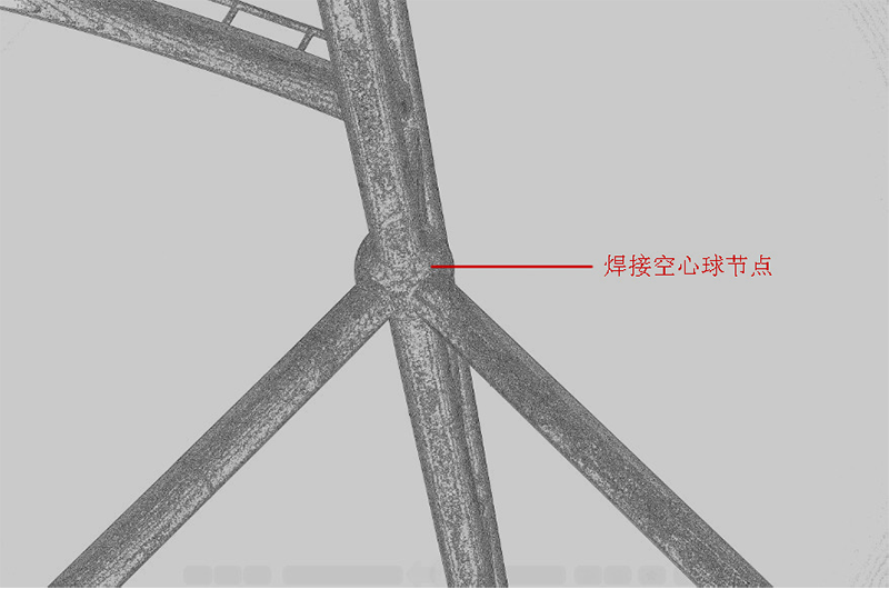
Welded Hollow Ball Node
5. Engineering measurement and calibration
The entire plane axis of the project is arranged in a fan shape at the center. The steel structure is hoisted on a concrete platform with 15 main structural columns along the radial main axis. The height of the structural columns is the same, and the height difference between the eaves of the primary and secondary trusses is + 10m.
The overall idea of surveying and positioning is to integrate the whole first and then to the local area. First, establish a plane construction control network and an elevation control network, adjust the observation structure to eliminate errors, and then perform detailed stakeout.
In order to simplify the engineering measurement of three-dimensional coordinates in complex space, a circle center point and thirty primary and secondary beam truss tips are used to design a projection point datum. A planar control network and thirty radial planes are used to form a measurement control system. The plane replaces the three-dimensional space to achieve accurate and fast measurement and positioning. A high-precision total station is selected, and a simple and effective hoisting unit correction process and step-by-step accuracy control methods are used to eliminate the adverse effects of cumulative errors and uneven settlement and displacement of the concrete structure on the installation of the steel structure.
3.3 Membrane structure technical measures
1. Construction process of single-layer roofing membrane structure
This stand membrane structure project is divided into a total of 28 pieces of membrane material, divided into 14 large units according to the structure column spacing, each large unit is divided into 2 small units. The fixed nodes of each film are in the form of aluminum alloy plate, and then fastened with stainless steel bolts.
The overall construction process of the membrane structure is: erection of the construction platform → layout of the rope net under the membrane → the membrane package is located directly below the deployed position → the membrane package is lifted to the structural roof → deployment of the membrane package → layout of the windproof rope on the membrane → temporary temporary fixing → membrane Surface perimeter fixation → film surface tension adjustment.
2. Special measures adopted for the structural characteristics of the engineering membrane
Because the main steel structure is up to 35m, the installation of the membrane structure has to be performed at a high altitude. At the same time, the site conditions cannot meet the requirements for the installation of full-scale scaffolding, which also greatly increases the difficulty of the construction of the membrane structure.
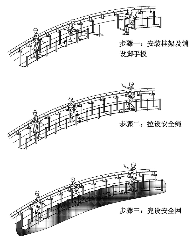
Consider the use of suspended scaffolding solutions for site operating conditions. The welded hanger is directly suspended from the position of the steel connecting plate by using the end hook. Welding hangers must be installed vertically on the ground during field installation. Safety ropes are provided on both the inside and outside of the hanger. A pair of anti-shake fiber ropes and secondary metal tendon ties are pulled every five hangers to prevent swing.
The operating platform installation steps are as follows:
⑴ Preparation: The operator attaches a double rope safety belt and a small rope of appropriate length to the steel pipe beam. The safety belt is reliably planted on the membrane pressing bottom plate. When the personnel moves, the two ropes must be alternately moved. A small rope is used to lift the pulley and one end of the big rope to the beam surface. The pulley is fixed on the press-fit bottom plate. The big rope bypasses the pulley and sends the rope head to the ground.
Hanger installation: Measure the relevant dimensions of each hanger one by one and notify the ground processing staff to perform the final processing of the hanger according to the required size immediately; use the pulley device to send the corresponding hanger to the installation position.
(3) Laying of wooden boards: According to the distance and slope of adjacent hangers, wooden scaffolding should be selected and tied with a short rope of about three meters at both ends, and the wooden boards should be sent to the beam by the pulley device. The two installers should hold the wooden boards respectively. The short ropes at both ends place the wooden board on the two racks smoothly. After placing two wooden board boards side by side in this way, the installer goes down to the board surface and fastens the wooden board to the rack with iron wire. Repeat the above steps and gradually advance until the entire scaffolding is completed, so that the hangers are integrated into a whole, so that the arches form a long and safe passage.
Guardrail and anti-swaying rope installation: Use plugging method to raise the outer riser of the hanger and fasten two safety ropes with big ropes on the riser; pull a pair of anti-swaying rope and two Secondary material rib plate tie.
⑸ After the suspension operation platform is set up, it can be officially used only after it is checked and confirmed by the safety officer.
Mounting instructions
Fourth, economic and technical indicators
The total steel volume of the project structure is 372.02t.
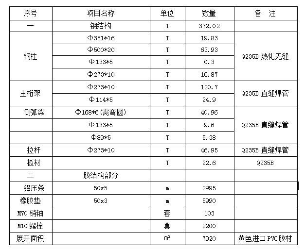
List of main materials
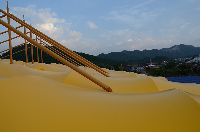
V. Engineering photos
After the stand is completed
The above is the introduction of the membrane structure of the "Storm and Storm" stands in the Dream Valley of Hengdian Film and Television City. If you have more questions about membrane structure engineering, you can contact Marriott for consultation and we will definitely give you a satisfactory answer.
Copyright © Zhejiang Wanhao Group Co., Ltd. All Rights Reserved.
Sitemap | Technical Support 