Search
Project Name: Ningbo Feishi Motor Technology Co., Ltd. Production Project of Various Permanent Magnet Servo Motors and Servo Drivers
Construction site: Ningbo City, Zhejiang Province
Completion time: June 2017
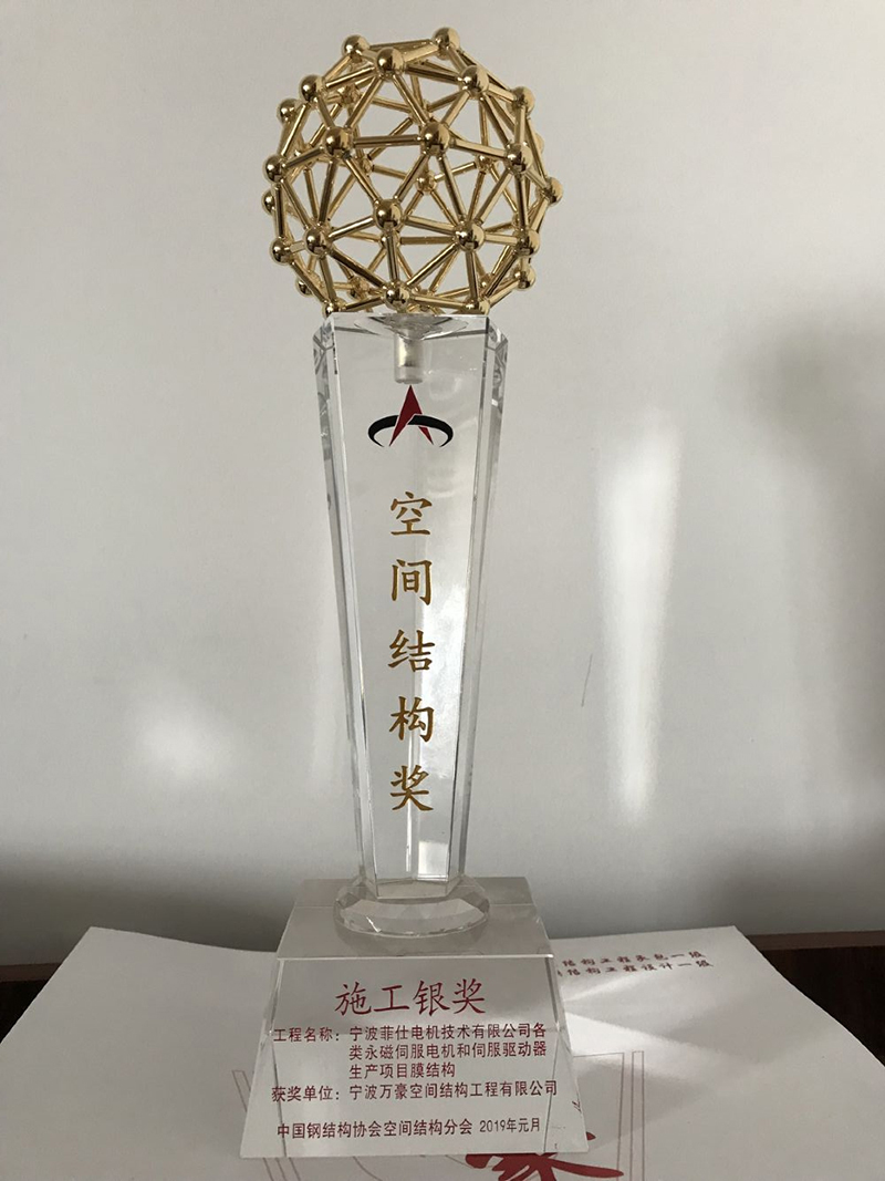
Award grade: Construction Silver Award
Winner: Ningbo Wanhao Space Structure Engineering Co., Ltd.
I. Project Overview
Ningbo Feishi Motor Technology Co., Ltd. various types of permanent magnet servo motors and servo drives production projects-membrane structure engineering project is located in Xiaogang Equipment Industrial Base, Beilun District, Ningbo City. The total construction area of the project is about 6000m2, and the three-dimensional grid height of the ground is 20.05 meters. The main steel structure adopts a pipe truss structure, and the connection nodes are connected by more than 1,500 welded hollow balls. The surface is covered with a PTFE mesh membrane and an overall triangular membrane. The unit is divided into about 3,000 units, and more than 7,000 steel rods of different shapes and sizes are combined. The surface unevenness and undulations have distinct shapes and shapes, which imposes high requirements on the precise positioning of steel pipe rods for spatial assembly. The elongation of the PTFE mesh film on the surface is very small, so high requirements are imposed on the accuracy control of the film cloth. Its unique shape design. The diversification of nodes has added a color to the Xiaogang Equipment Industrial Base in Beilun District, Ningbo City, and has become an iconic membrane structure building.
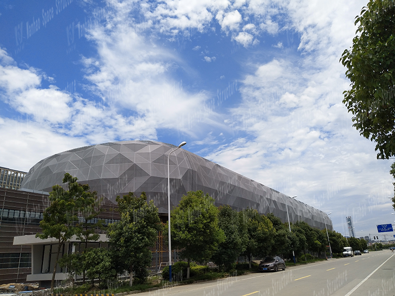
Figure 1 Membrane Structure Engineering
The project was further designed, manufactured and installed by Ningbo Wanhao Space Structure Engineering Co., Ltd. The project was completed on June 30, 2017.
Structural system
The project is a skeletal membrane structure with a total construction area of about 6000m2 and a three-dimensional grid height of 20.05 meters above ground. The main steel structure adopts a pipe truss structure, and the connection nodes are connected by more than 1,500 welded hollow spheres; the surface is covered with PTFE mesh membrane material, the overall triangular membrane unit is divided into about 3000, and more than 7,000 steel rod members are of different shapes and sizes. .
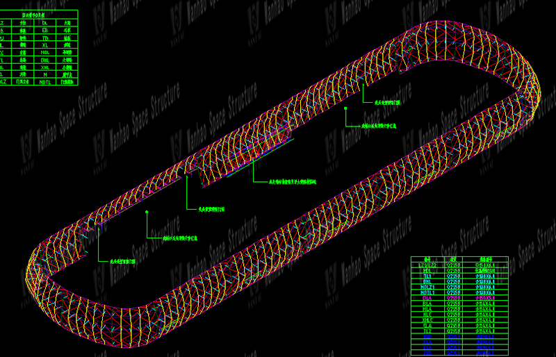
Figure 2.Single bobbin side view of the overall structure
Third, technical measures
Construction difficulties of this project
The owner requires on-site cross construction, the work surface is complex, and the construction period is short; due to the special shape of the project, the unevenness, the shape of the height fluctuations, the component nodes meet many rods, and the use of ordinary pipe-to-pipe intersecting nodes cannot meet the design at all Requirements and meet the requirements of "diamond" design aesthetics, so we use welding hollow ball node connection method at these nodes in the design process. The node meets 4 members, with a large number of members and a small diameter. The smallest member has a diameter of 89mm. The geometry of the node is shown in Figure 3. Because this type of node is connected to the spherical surface of the steel pipe, the surface of the hollow ball provides more welding space for the weld of the steel pipe. At the same time, this is why the hollow ball is selected as the fixed weld;
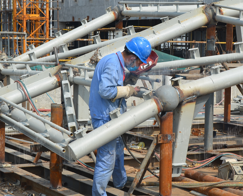
Figure 3 Node geometry
In order to meet the design requirements to achieve overdue visual effects, the overall project is divided into more than 3,000 triangular membrane units, the minimum membrane unit is less than 2 square meters, and the single membrane unit is smaller, which adds greater difficulties to construction and processing; meanwhile, the mesh membrane structure is different Compared with other types of membrane structures, the expansion and contraction margin is small, so the dimensional accuracy requirements are extremely high. A slight deviation can easily cause a series of problems such as wrinkling of the membrane surface and the boundary exceeds the design value. Therefore, we installed and installed the steel structure in the construction site. At the same time, a full-time surveyor is assigned to monitor and review the dimensions with a total station to ensure that the size of each component is controlled within the tolerance allowed by the specification.
2. General installation steps
The first step: After the factory has shipped the produced steel structure members to the site, they are stacked in different categories and a spliced tire frame is set up on the open space.
The second step: the components in a span area are assembled on the tire frame to make a whole.
Step 3: Sand the welded joint of a unit and apply paint.
The fourth cloth: the completed single-span unit is fixed to the building facade with a crane.
Step 5: The gaps between the hoisted units are spliced in bulk at high altitude.
Step 6: Install all PTFE mesh membranes on all steel structures.
3. Steel structure installation and construction process
Construction area division: counterclockwise flow along the circular pavilion: A → B → C → D → E → F → G → H.
Construction and installation steps: measurement and calibration of embedded parts → welding of hinged lugs of embedded parts → bolt fixing of bull's leg → hoisting of main structure → hoisting of connecting beams and diagonal braces → hoistway installation → membrane structure installation
Construction and installation measures: According to the site conditions, use tower cranes to carry out flowing construction according to the divided construction areas; configure a QY25 truck crane as a vertical lifting and transportation tool for auxiliary lifting in places where the tower cranes cannot be hoisted; The embedded parts are not pre-buried, and secondary reinforcement is needed. The exhibition hall has no outer scaffolding. Temporary scaffolding will be set up during the construction process, and secondary reinforcement and bull's legs will be fixed.
4. General idea of installation plan
This project intends to adopt the classification hoisting method. The characteristics of the classification hoisting method are that the construction content is single and the preparation work is simple. Therefore, the component hoisting efficiency is high and easy to manage. The selected tower crane meets various component hoisting. Where the tower crane cannot be hoisted, The crane is selected, and the traveling route of the crane is according to the one-way hoisting method. This route method has high work efficiency. According to the divided construction area, the crane's outriggers are located at the central axis of the two lifting partitions each time, and the components enter the site one by one according to the factory number. On the site, a temporary assembly platform is set up to separate the two sides of the crane so that the steel components are within its working range. In this way, the trouble of secondary transportation can be avoided, and it also brings convenience to structural lifting. In this project, some areas cannot be hoisted by cranes. Therefore, the maximum hoisting weight of the tower crane should be considered in the area hoisted by the tower crane. North elevation ④ axis to ⑲ axis. The lifting weight of the front end of the tower crane is controlled within one ton, and the remaining tower cranes are not hoisted with a 25-ton car crane for lifting.
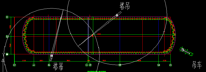
Figure 4 Schematic diagram of hoisting range of tower crane
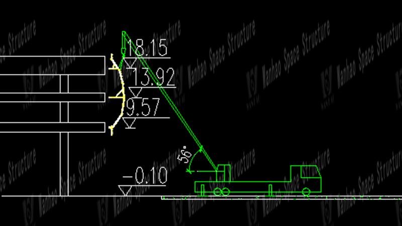
Figure 4 Crane hoisting
5, steel structure installation steps
Measurement and correction of embedded parts → Rebar reinforcement → Welding of articulated lugs of embedded parts → Bolt fixing of main legs → Hoisting of main structure → Hoisting of connecting beams and diagonal braces → Installation on the road.
6.Measurement and correction of embedded parts
Before the main steel structure is installed, the pre-embedded parts that have been pre-buried need to be positioned and re-tested. At the same time, the partially-embedded pre-embedded parts are anchored to ensure the accuracy of the main steel structure. This project will use a high-precision total station to re-lod out the embedded parts, and accurately display the axis control mark on the steel plate as shown in Figure 5.
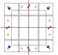
Figure 5 Embedded control axis identification
Part of the embedded parts on the facade of the exhibition hall is not embedded in advance, and it is necessary to re-plant the reinforcement. At the same time as the positioning of the embedded parts is retested, the coordinates of the missing parts are staked out one by one on the concrete wall of the facade. Anchored. Before anchoring the iron plate, the welding work of the hinged lugs should be completed in advance to avoid high temperature damage to the chemicals.
7. Hinged lug welding of embedded parts
After the positioning and retesting of the embedded parts is completed, the welding hinged ear plate needs to be controlled along the axis as shown in Figure 6.
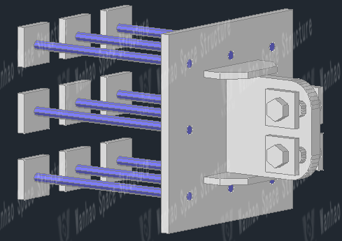
Figure 6 Hinged Ear Plate Welding
8. Corbel bolt
After the hinged lugs are welded, they can be directly bolted to the corbel as shown in Figure 7. Because the hinged lugs are oblong holes, you need to adjust the vertical, horizontal, and length of the corbels while fixing to ensure the square tube cross section is consistent.
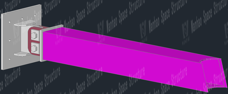
Figure 7
9. Hoisting of main structure
After the local corbel is fixed, the main structure can be hoisted. Based on the structural features of this project, the main structure will be installed on the ground and assembled as a whole. An assembly platform will be set up on the ground, and the bone of a unit will be assembled directly on the platform, as shown in Figure 8, and then lifted by a tower crane or crane as a whole, and the dimensions will be determined by the limit plate, which will be directly welded to the thigh. Photo of construction site.

Figure 8 Assembled skeleton
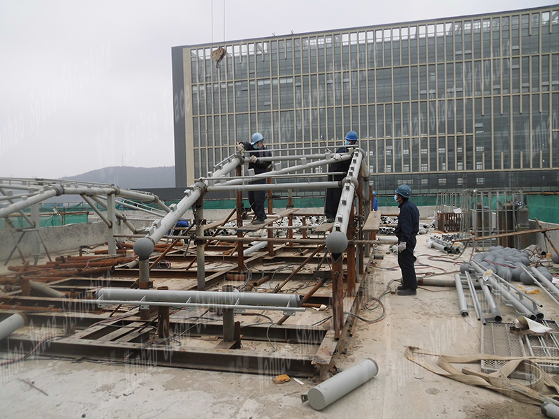
Figure 9 Assembly of steel structural units
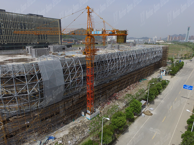
Figure 10 Skeleton diagram of the steel structure
Fourth, the membrane installation and construction process
Membrane structure installation steps
The film package is in place → the film package is unfolded → the splint is temporarily fixed → the diaphragm is lifted → the aluminum alloy Fastener is assembled → the tension adjustment is performed → the aluminum alloy Fastener is fixed.
Before the membrane body is installed on the site, the relevant project personnel are organized to review the construction plan and determine the detailed installation operations and safety technical measures. Review the various dimensions of the support structure, so that the installation error of each control point is within the range allowed by the design and specifications; check the membrane body and accessories; check whether the appearance of the membrane body is damaged, wrinkled, and whether the thermal fusion seam has fallen off. Whether the bolt, aluminum alloy bead and stainless steel bead are damaged or rusted, and whether the cable and anchor coating are damaged.
2. Installation process
The installation of the membrane body includes four parts: expansion of the membrane body, connection and fixing, lifting in place, and tension forming.
The process of membrane installation is as follows: determination of the installation plan → review of the supporting structure dimensions → inspection of the membrane installation technology → check whether the installation equipment and tools are in place → erection of the installation platform → laying of protective cloth → unfolding of the membrane → connection and fixing → lifting membrane → adjustment cable and membrane Edge closing → Tension forming → Waterproof treatment → Washing the film surface → Final inspection → Handover.
The main structure of this project is high, so that the installation of the membrane structure has to be performed at high altitudes. At the same time, considering the site operating conditions, we will consider the use of a hanging scaffolding scheme. The welded hanger is directly suspended from the position of the steel connecting plate by using the end hook. Welding hangers must be installed vertically on the ground during field installation. Safety ropes are provided on both the inside and outside of the hanger. A pair of anti-shake fiber ropes and secondary metal tendon ties are pulled every five hangers to prevent swing.
The operating platform installation steps are as follows:
Preparation: The operator attaches a double rope safety belt and a small rope of appropriate length to the steel pipe beam. The safety belt is planted on the bottom of the membrane press-fitting base. The personnel must alternately move the double roots when they move. A small rope is used to lift the pulley and one end of the big rope to the beam surface. The pulley is fixed on the press-fit bottom plate. The big rope bypasses the pulley and sends the rope head to the ground.
Installation of hangers: Measure the relevant dimensions of each hanger one by one and notify the ground processing staff to perform the final processing of the hangers according to the required size immediately; use the pulley device to send the corresponding hangers to the installation position.
Laying of wooden boards: According to the distance and slope of the adjacent hangers, select wooden scaffolding and tie a short rope of about three meters at both ends. Use a pulley device to send the wooden boards to the beam. The two installers hold the two ends of the wooden boards respectively. The short rope puts the wooden board on two hangers smoothly. After placing the two wooden boards side by side in this way, the installer descends to the board surface and fastens the wooden board to the hanger with wire. Repeat the above steps and gradually advance until the entire scaffolding is completed, so that the hangers are integrated into a whole, so that the arches form a long and safe passage.
Installation of guardrail and anti-swaying fiber rope: use plugging method to raise the outer riser of the hanger and fasten two protective safety ropes with large ropes on the riser. Tie ribs on the ribs.
After the suspension operation platform is set up, it can be officially used only after being checked and confirmed by the safety officer.
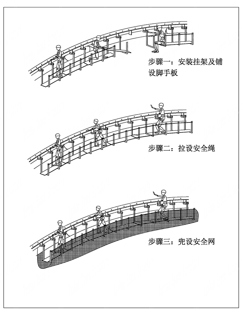
Figure 11 Operating platform installation steps
V. Economic and technical indicators
The total amount of steel used in this engineering structure is about 200T, and the amount of film used is 6,500m2. The material table is shown in Table 2.
Table 2 List of main materials
project
specification
Material
Quantity
Main pole
Φ159 × 6
Q235B straight seam welded steel pipe
98.8T
Secondary shot
Φ89 × 4 ~ 114 × 4
Q235B straight seam welded steel pipe
80.6T
Aluminum profile
Custom specifications
T6061
8000M
Membrane
Tensile strength ≧ 3500N
PTFE mesh membrane (glass fiber)
6500M2
Project photos
Figure 12-14 is a photo of the construction process.
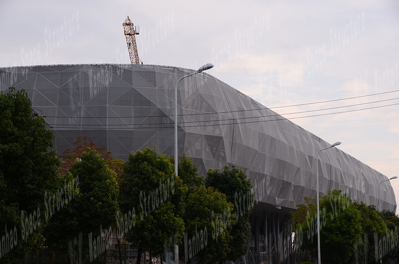
Figure 12 Engineering side elevation
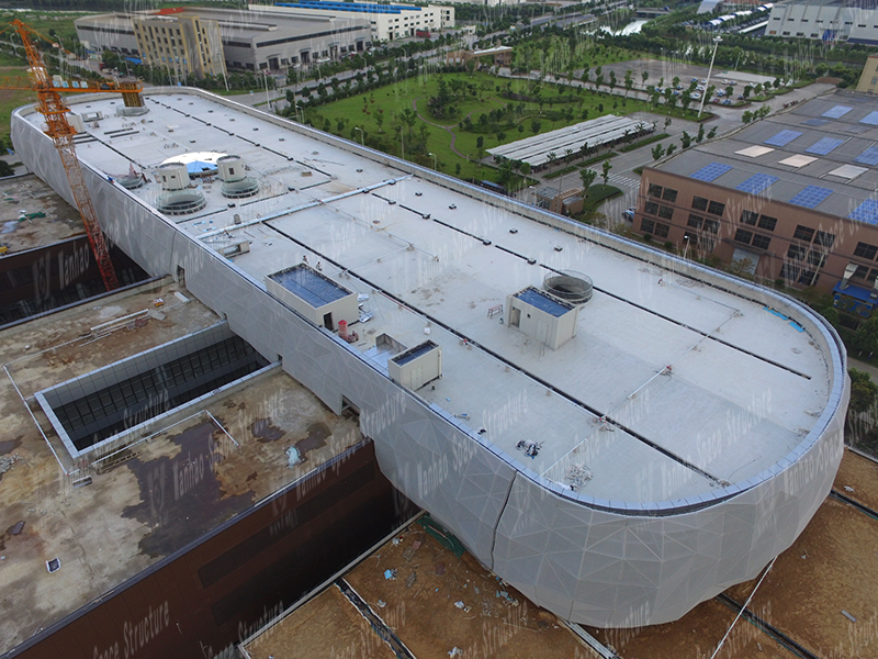
Figure 13 Project elevation

Figure 14 Top view of the project
The above is the relevant introduction of the PTFE mesh membrane structure project of the Faith Motor Facade. If you have more questions about membrane structure engineering, you can contact Wanhao for consultation and we will definitely give you a satisfactory answer.
Copyright © Zhejiang Wanhao Group Co., Ltd. All Rights Reserved.
Sitemap | Technical Support 